Kansas City's built environment is defined by its geology: a Pennsylvanian-age sequence of interbedded limestones and shales blanketed by Pleistocene glacial drift and thick Missouri River alluvium. What works structurally in the Crossroads Arts District may be entirely inadequate north of the river in Clay County, where paleochannels filled with compressible clays and loose sands lie hidden beneath industrial parks built in the 1970s expansion. Vertical Electrical Sounding (VES) cuts through this ambiguity. By injecting a controlled DC current through a four-electrode array and measuring the resulting potential difference, the method resolves vertical resistivity profiles that differentiate fresh limestone bedrock from weathered shale, saturated sand lenses from stiff glacial till, and intact rock from karst-affected zones. When we run a 400-meter Schlumberger spread across a site in the Blue River valley, the resulting apparent resistivity curve—processed through 1D inversion software using a Marquardt-Levenberg algorithm—reveals the contact between the Argentine Limestone and the underlying Lane Shale at depths exceeding 100 feet, information that conventional borehole programs often miss between widely spaced drill points. The technique becomes particularly powerful in the Kansas City metro because the electrical contrast between brine-saturated Pennsylvanian shale (often below 15 ohm-m) and competent Winterset Limestone (above 200 ohm-m) is sharp enough to map karst dissolution features that threaten foundation stability across Jackson County.
The electrical contrast between Pennsylvanian shale and competent limestone in Kansas City produces a resistivity signature sharp enough to map dissolution features that conventional borings routinely miss.
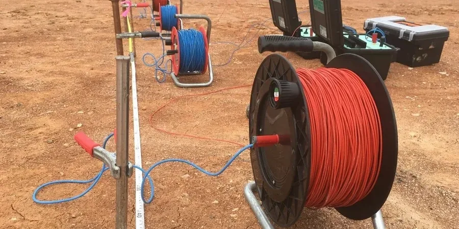
Our approach and scope
Local considerations
Three years ago we were called to a site near the former Richards-Gebaur Air Force Base in south Kansas City where a proposed warehouse slab had developed differential settlement within six months of construction. The original geotechnical report, based on six borings across a 12-acre parcel, had classified the site as stiff clay overlying sound bedrock at 28 feet. A quick 800-foot VES traverse told a different story: apparent resistivity values below 8 ohm-m at depths between 35 and 50 feet indicated a buried channel filled with saturated, organic-rich clay that had consolidated unevenly under fill loads. The boring pattern had simply missed the feature. Resistivity imaging further revealed that the channel's thalweg ran diagonally under the southwest corner of the building—exactly where cracking was concentrated. The cost of remediation was significant, but the VES data prevented it from becoming a litigation problem. Across the Kansas City region, undocumented paleovalleys carved into the bedrock surface during Pleistocene lowstands remain one of the most underestimated geotechnical hazards; they are invisible to sparse drilling programs because they meander unpredictably. VES provides the only practical means of mapping these features continuously between boreholes, and for that reason it has become standard practice for any structure exceeding two stories in the Missouri River floodplain.
Video overview
Relevant standards
ASTM D6431-18: Standard Guide for Using the Direct Current Resistivity Method for Subsurface Site Characterization, ASTM D5777-18: Standard Guide for Using the Seismic Refraction Method for Subsurface Investigation, IBC 2021 Section 1803: Geotechnical Investigations, ASCE 7-22 Chapter 20: Site Classification Procedure for Seismic Design
Associated technical services
1D Vertical Electrical Sounding (Schlumberger array)
Depth-specific resistivity profiling to 150 ft for mapping bedrock surface, paleochannel geometry, and karst features. Includes apparent resistivity curve generation and Occam inversion with layer-thickness interpretation.
2D Electrical Resistivity Tomography (ERT)
Multi-electrode dipole-dipole and Wenner-Schlumberger arrays for continuous cross-sectional imaging along linear transects up to 800 ft. Applied to levee investigations, landfill boundary delineation, and fracture-zone mapping.
Combined VES and seismic refraction
Co-located resistivity and P-wave refraction lines to resolve ambiguities between lithologic and fluid-content controls on resistivity. Typical for sites where brine contamination or saline groundwater is suspected.
Karst susceptibility mapping
Grid-based VES with 50–100 ft station spacing to delineate dissolution-prone zones in the Argentine and Bethany Falls limestone members. Output includes iso-resistivity contour maps at target depths for foundation planning.
Typical parameters
Quick answers
What depth of investigation can VES achieve in the Kansas City area?
With a maximum current-electrode half-spacing (AB/2) of 200 feet, we routinely achieve investigation depths of 120 to 150 feet in Kansas City formations. Depth penetration is controlled by the AB/2 spread length and by the resistivity structure itself; conductive near-surface clays in the Missouri River floodplain attenuate current and reduce effective depth compared to the resistive limestone uplands of Johnson and southern Jackson counties. For deeper targets, we extend the spread or switch to 2D electrical resistivity tomography with longer arrays.
How do you distinguish between a water-filled karst cavity and a shale layer on a VES profile?
Both features produce low resistivity, but their context and geometry differ. Shale layers in the Kansas City Pennsylvanian section are laterally continuous and produce consistent low-resistivity deflections across multiple soundings; karst cavities are localized and cause abrupt, isolated drops in apparent resistivity that do not correlate from one VES station to the next. We cross-check ambiguous cases with MASW or seismic refraction—a water-filled cavity shows a sharp shear-wave velocity drop, while intact shale generally retains higher stiffness. Borehole control, even from a single location, resolves the final ambiguity.
What is the typical cost range for a VES survey in Kansas City?
For a standard VES program involving 6 to 10 individual soundings on a typical commercial parcel in the Kansas City metro, costs generally fall between US$680 and US$1,150 per sounding, depending on spread length, terrain accessibility, and whether 2D tomographic profiles are included. A full-day mobilization with 2D ERT along two 400-foot lines typically runs at the upper end of that range. Site-specific variables—surface pavement, buried utilities, steep slopes in the Blue River corridor—can influence final pricing.
What ASTM standard governs resistivity surveys, and does it apply to Kansas City projects?
ASTM D6431-18, the Standard Guide for Using the Direct Current Resistivity Method for Subsurface Site Characterization, is the governing standard. It establishes procedures for electrode array selection, data acquisition quality control, inversion methodology, and reporting. All resistivity work we perform in the Kansas City metro follows D6431-18, and our deliverables include the required documentation: sounding curves, modeled layer parameters with RMS error, and interpreted geologic cross-sections tied to available borehole data. More info.